
Descripción
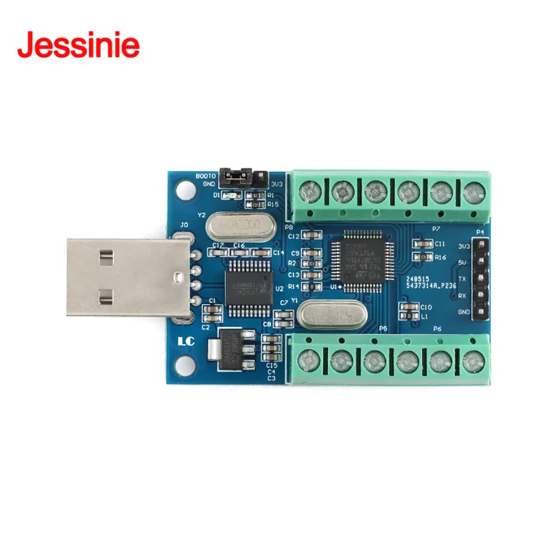
STM32F103C8T6 USB Interface 10 Channel 12Bit AD Sampling Data Acquisition STM32 UART Communication ADC Module
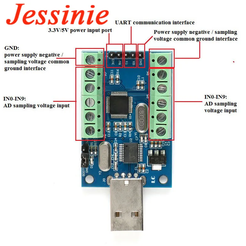
Product FeatureThe 10-channel ADC module uses the internal 10-channel ADC resources of the STM32F103 series as the sampling core, and transfers the acquired sampling data to the internal memory through the STM32 to reduce the CPU load and enhance the stability of the AD sampling. Accuracy, while the onboard USB to serial port chip can transfer data to the host computer.Product ParameterOnboard STM32F103C8T6 master chipOn-board CH340 serial port to USB chip, easy to view AD sampling results on PC through USB portReserved UART serial communication interface, can be connected to MCUAnalog input channel, 10-channel single-ended inputSampling voltage input range: 0~3.3VPower supply voltage: 5V/3.3VResolution: 12Bit (4096)Board size: 50*33mmInstructions For Use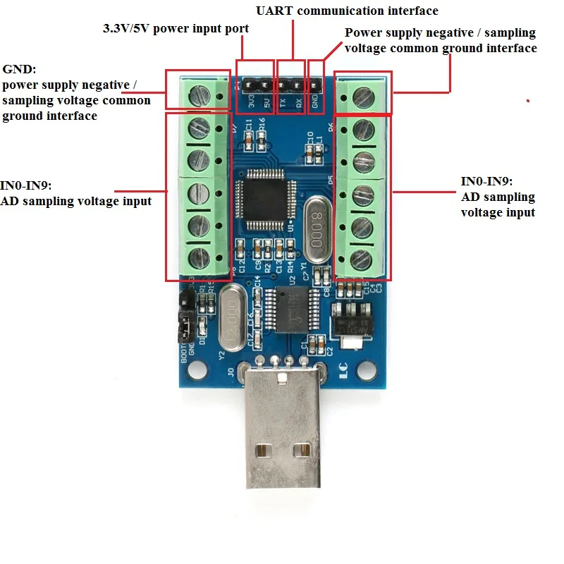
Install the USB to serial port chip CH340 driver, plug the module into the computer, IN0-IN9 is connected to the sampling voltage positive, GND is connected to the sampling voltage negative (ie, common processing), open the serial debugging assistant, select the correct COM port and baud rate ( 115200), you can view the AD sampling result, the sampling result is refreshed once in 500ms, the customer can modify this time on the basis of the source code.
If you want to use the external MCU to obtain the sampling data directly, you can connect the 3.3V, RX, TX, and GND of the MCU to the 3.3V, TX, RX, and GND of the module. Of course, it is ok to supply the module with 5V. The protocol for data transfer can be found by looking at the source code.
If the customer wants to modify the source code, re-program the program.
The method is as follows: Insert the module into the USB port of the computer, insert the jumper cap on the module to the 3V3 end (note that it should be plugged back to GND after the programming is completed), open the programming software FlyMcu, open the hex file, set the port number and wave. For the relevant parameters such as the special rate, click “Start Programming”, then use the tweezers to clamp the two ends of the capacitor C9 (equivalent to reset).
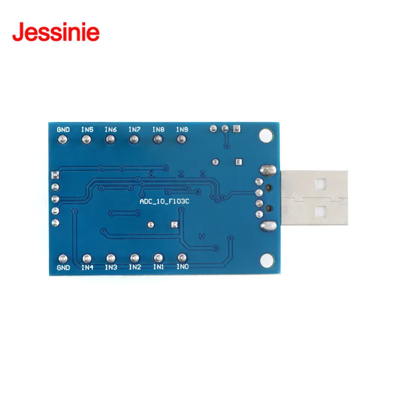
The sampling voltage input terminals IN0-IN9 can be connected or only partially connected. When a certain channel has no sampling voltage input, the output of the channel is a random value, and the unused port can also be modified by itself as a normal I/O port.
The voltage used should not exceed 3.3V, otherwise there is a possibility of damage to the chip.