
En Stock
4,59 €
Con la garantía de 
Color
23 unidades vendidas
Última actualización: 2026-04-08T00:30:53.936Z
Descripción

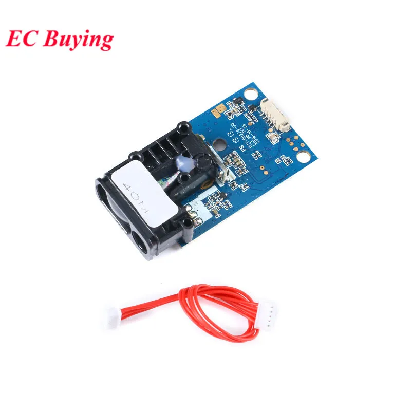
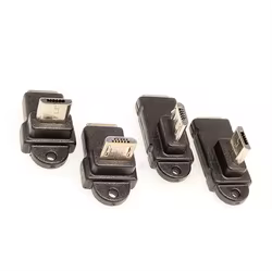
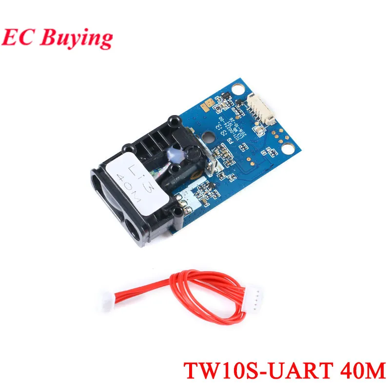
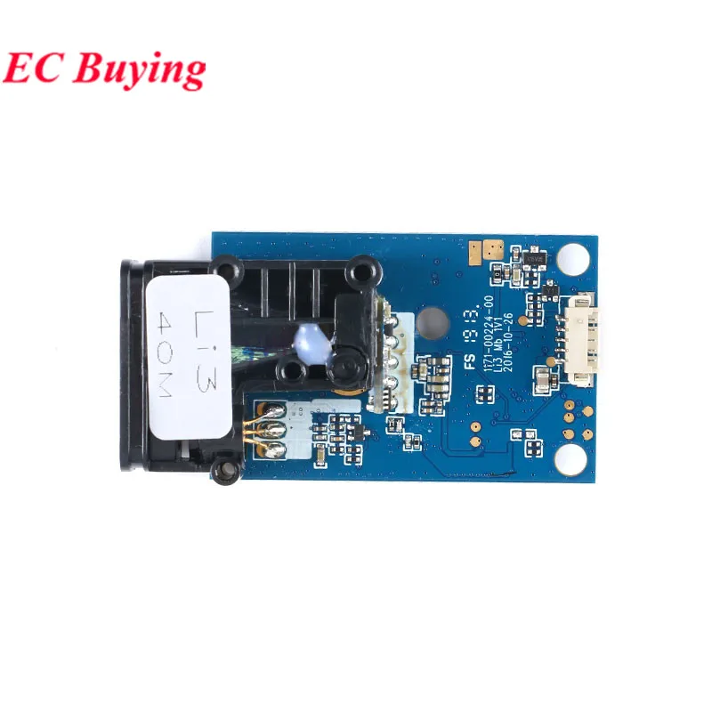
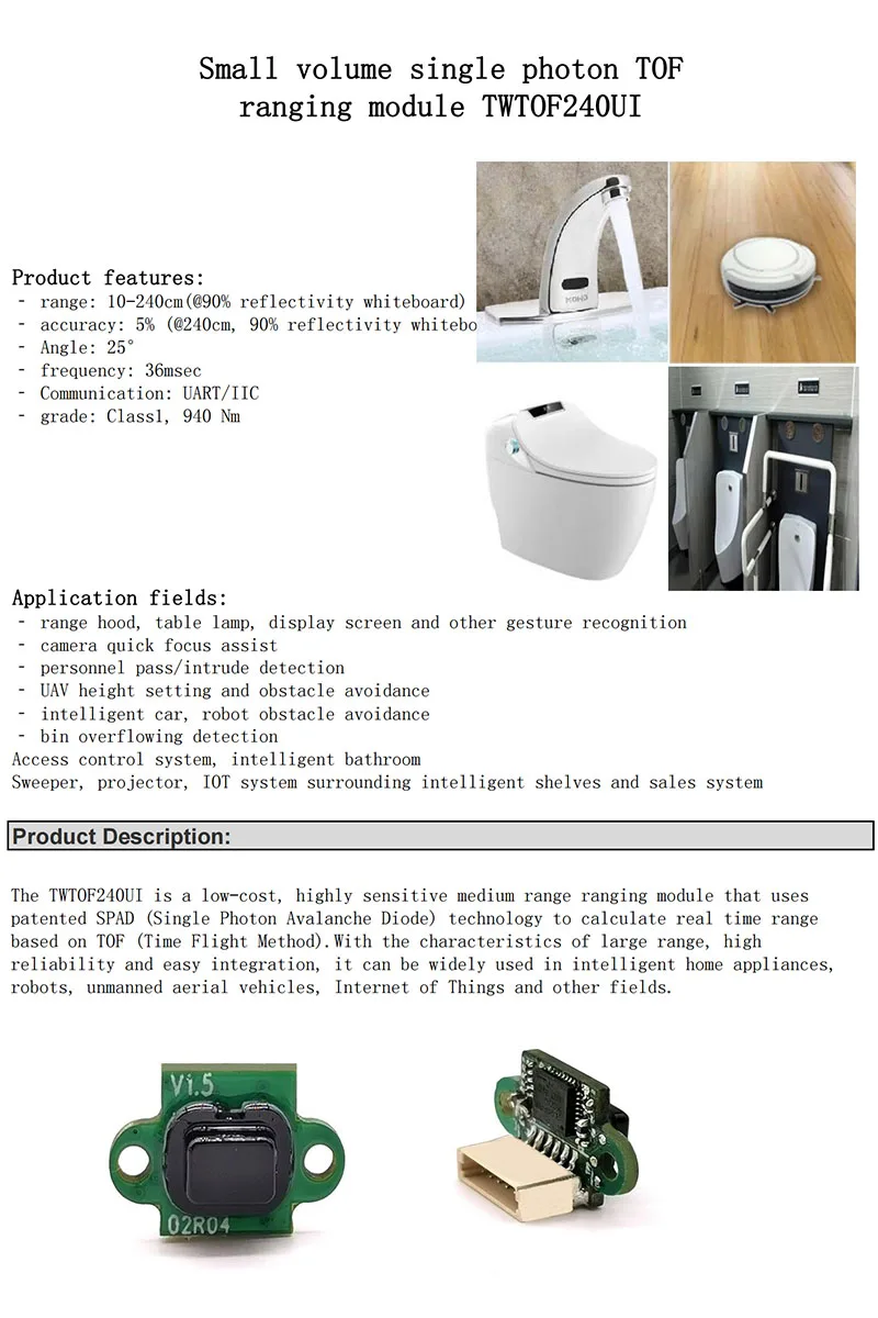
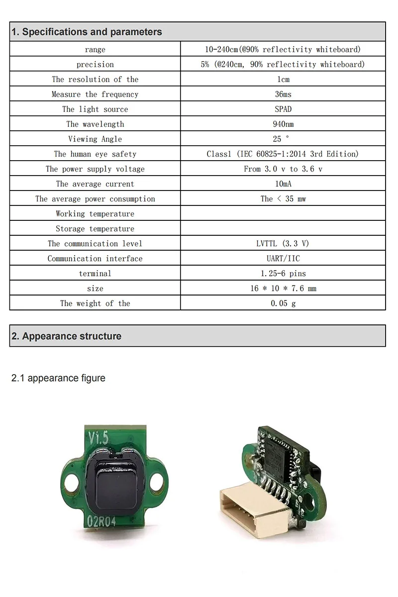
Technical Parameters:Interface: 3.3V-5V / TTL232 three-wire serial interface (ie single-chip UART / USART / SCI interface, please do not directly connect RS232 interface!).Baud rate: (4800, 9600, 19200, 38400, 57600, 115200) optional, default 38400Power supply voltage: 3.3V;Working current: 180mA;Measuring range: 0.04 ~ 40m (based on the front of the module)Measurement speed: up to 5HZ, that is, 5 data can be measured within 1s;Measurement accuracy: ± 2mm + 5 * 10 (-5) D, where D is the measurement distance;Operating temperature: -10 ~ 50 ℃;Storage temperature: -30 ~ 70 ℃;Product size: 60 * 31 * 14mm (length * width * height);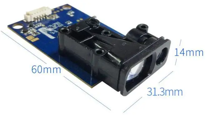 Connection diagram:Description: 1-EN_PWR // *** High level (3.3V ~ 5V) enable terminal, set high level for normal operation, set low levelWhen the machine is in a low power state *** //2-RX // *** communication receiving end *** //3-TX // *** communication sender *** //4-GND // *** signal ground, and negative power supply port *** //5-3.3V // *** Power supply “positive” port *** //
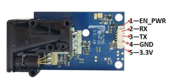 Installation Notes:1. Please do not loosen the 4 screws of the PCB circuit board, that is, loosening and stress after precision focus adjustment may cause irreparable defocus problems!2. For fixing, you can use the three round holes left on the module for fixing. Please do not apply obvious external force to the circuit board or squeeze or distort the optical structure.3. The module should not be used for a long time under strong vibration environment. If installed in a use environment with obvious vibration, the front end should have a certain soft fixation.4. Care should be taken to keep the entire optical path of the module clean. Laser tube windows, small transmitting lenses, large receiving lenses, housing windows, and other optical lenses should be kept clean. Do not expose the module to dusty environments, and do not touch the transmitting and receiving lenses with your fingers. Especially when measuring long distance or weak reflection targets, the lens contamination will obviously or seriously affect the measurement! Contaminated lenses can be blown off with a strong skin to remove surface particles and floating dust, and then wipe it with a soft paper with a small amount of dust. Do not wipe it back and forth, and do not touch it with the paper or the place where it has been rubbed. Wipe the lenses! Do not wipe the transmitting and receiving lenses with liquids that are not suitable for PMMA resin lenses!Outdoor use instructions:1. The ability of the module to measure outdoors during the day is significantly reduced, especially in the sun. Therefore, it should cooperate with a special reflective plate or reflective film. However, the reflection film may cause excessive signal when measuring within 10 meters.2. Direct sunlight on the lens of the module, or direct reflection surface with an angle of less than 45 degrees from the laser beam exit direction, may make it impossible to measure. Rain and snow can also make it impossible to measure.3, whether indoor or outdoor, avoid reflecting surface is mirror or transparent and translucent unless special use.V. Instructions for use of the upper computerIf necessary, you can ask the customer service for an upper computer software package after placing the order. You can also use the serial debugging tool, which can be selected according to your own needs. You can also ask our customer service for the installation package of the serial debugging tool. Of course, you can also download it online.PC software interface
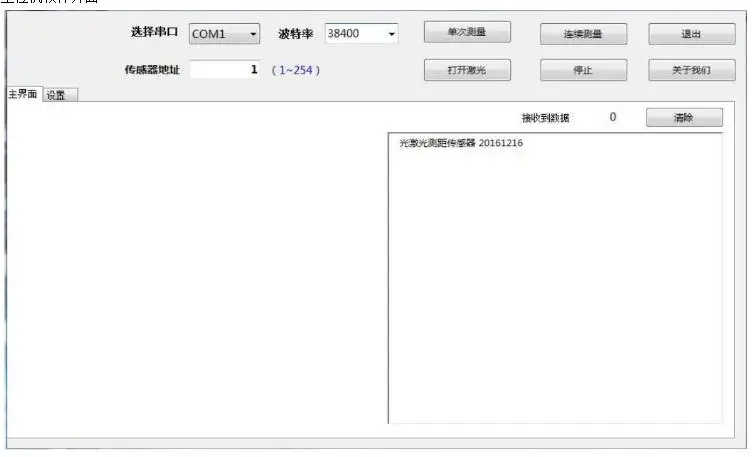 1. First make sure that the machine is powered normally, and then the serial communication is normal, select the corresponding COM port, enter the address of the current machine in the "Sensor Address" column (the default is 1), and then select the corresponding baud rate (the default is 115200, users can change according to their needs during use);2. Click the single measurement button, the laser will flash once, and the distance information currently measured will be displayed in the blank area on the right side of the software.3. Click continuous measurement, the laser will flash continuously, and then the measured distance data will be output on the right display area.4. Click to turn on the laser. The laser will stay on, but will not measure distance. Users can use this function to aim at the measured object.5. Click the setting button to enter the following interface, which is mainly used to configure some parameters of the machine;
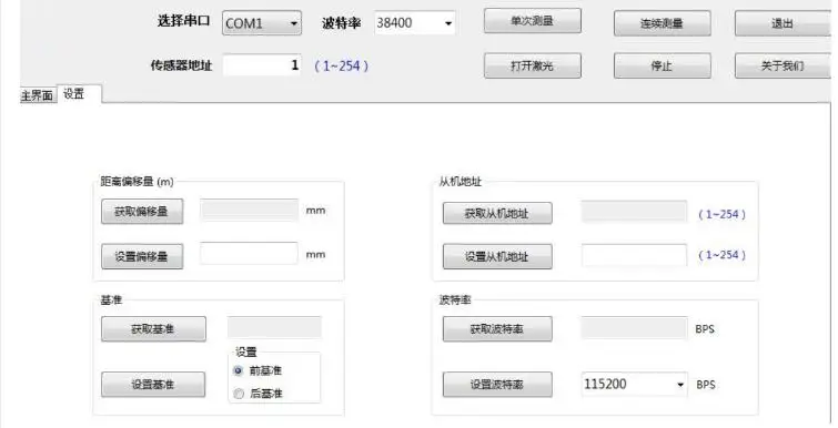


Connection diagram:Description: 1-EN_PWR // *** High level (3.3V ~ 5V) enable terminal, set high level for normal operation, set low levelWhen the machine is in a low power state *** //2-RX // *** communication receiving end *** //3-TX // *** communication sender *** //4-GND // *** signal ground, and negative power supply port *** //5-3.3V // *** Power supply “positive” port *** //Installation Notes:1. Please do not loosen the 4 screws of the PCB circuit board, that is, loosening and stress after precision focus adjustment may cause irreparable defocus problems!2. For fixing, you can use the three round holes left on the module for fixing. Please do not apply obvious external force to the circuit board or squeeze or distort the optical structure.3. The module should not be used for a long time under strong vibration environment. If installed in a use environment with obvious vibration, the front end should have a certain soft fixation.4. Care should be taken to keep the entire optical path of the module clean. Laser tube windows, small transmitting lenses, large receiving lenses, housing windows, and other optical lenses should be kept clean. Do not expose the module to dusty environments, and do not touch the transmitting and receiving lenses with your fingers. Especially when measuring long distance or weak reflection targets, the lens contamination will obviously or seriously affect the measurement! Contaminated lenses can be blown off with a strong skin to remove surface particles and floating dust, and then wipe it with a soft paper with a small amount of dust. Do not wipe it back and forth, and do not touch it with the paper or the place where it has been rubbed. Wipe the lenses! Do not wipe the transmitting and receiving lenses with liquids that are not suitable for PMMA resin lenses!Outdoor use instructions:1. The ability of the module to measure outdoors during the day is significantly reduced, especially in the sun. Therefore, it should cooperate with a special reflective plate or reflective film. However, the reflection film may cause excessive signal when measuring within 10 meters.2. Direct sunlight on the lens of the module, or direct reflection surface with an angle of less than 45 degrees from the laser beam exit direction, may make it impossible to measure. Rain and snow can also make it impossible to measure.3, whether indoor or outdoor, avoid reflecting surface is mirror or transparent and translucent unless special use.V. Instructions for use of the upper computerIf necessary, you can ask the customer service for an upper computer software package after placing the order. You can also use the serial debugging tool, which can be selected according to your own needs. You can also ask our customer service for the installation package of the serial debugging tool. Of course, you can also download it online.PC software interface1. First make sure that the machine is powered normally, and then the serial communication is normal, select the corresponding COM port, enter the address of the current machine in the "Sensor Address" column (the default is 1), and then select the corresponding baud rate (the default is 115200, users can change according to their needs during use);2. Click the single measurement button, the laser will flash once, and the distance information currently measured will be displayed in the blank area on the right side of the software.3. Click continuous measurement, the laser will flash continuously, and then the measured distance data will be output on the right display area.4. Click to turn on the laser. The laser will stay on, but will not measure distance. Users can use this function to aim at the measured object.5. Click the setting button to enter the following interface, which is mainly used to configure some parameters of the machine;Set the offset: For example, if you want the machine to measure 5cm more than the actual distance each time, you can output 50 in the side box, and then click the Set offset button, and you will be prompted to set it successfully. Similarly, if you want to measure 5cm less each time, enter "-50".Setting the benchmark: It is generally recommended to set the benchmark before, that is, counting from the front of the module. This function can be replaced by the function of "setting the offset".Set the slave address: When you are online, you can set a different address for each machine, from 1 to 254.Set baud rate: You can set the required baud rate according to the user's own needs. The default is 38400.Serial assistant setting instructions:Select the correct COM port—select the correct baud rate—data bit 8—check bit None—receive select Hex—send select Hex, and then send the correct command according to the protocol to measure the distance normally. .Protocol instruction description:1: The sensor is ready to continueBefore each ranging, set the EN pin to high level (3.3V ~ 5V), the sensor will be woken up and initialize the hardware, the sensor will continue to issue the followingResponse:01 03 02 00 00 B8 44Set EN low after the measurement is completed, and the sensor enters low power mode.2: Read the input register (function code 0x03) (Before issuing this command, wait for the sensor to continue)Example:Read measurement distanceDescription Address code Function code Start address Number of registers CRCSend: 0x01 0x03 0x00 0x0F 0x00 0x02 0xF4 0x08Normal response (measurement distance 57.505m):Description Address code Function code Number of bytes Register 1 value Register 2 value CRCNormal response: 0x01 0x03 0x04 0x00 0x00 0xE0 0xA1 0x72 0x4BNote (the distance in this instruction is 4 bytes, 0x00 0x00 0xE0 0xA1, and the distance is 0x0000E0A1, converted to 57505mm in decimal)If the start address is wrong, the response is as follows:Description Address code Error code Exception code CRCError response: 0x01 0x83 0x02 0xC0 0xF1 (wrong start address)4: Error codeUnder normal ranging conditions:Send read measurement distance (single measurement)Description Address code Function code Start address Number of registers CRCSend: 0x01 0x03 0x00 0x0F 0x00 0x02 0xF4 0x08Normal response (measurement distance 57.505m):Description Address code Function code Number of bytes Register 1 value Register 2 value CRCNormal response: 0x01 0x03 0x04 0x00 0x00 0xE0 0xA1 0x72 0x4BNote (the distance in this instruction is 4 bytes, 0x00 0x00 0xE0 0xA1, and the distance is 0x0000E0A1, converted to 57505mm in decimal)When an error occurs, registers 1 and 2 represent the error code. The specific types are as follows:0xFF000000 Calculation error, remeasure0xFE000000 The reflected light is weak or the measurement time is too long, the reflecting surface should be more easily reflected, orWith chopping board, blank paper, etc.0xFD000000 Target is too reflective, do not aim at strong light0xFC000000 range exceeded, please measure within the range of the instrument5: CRC16 calculation source1.CRC check code calculation table:/ * CRC high byte value table * /const u8 auchCRCHi []={0x00, 0xC1, 0x81, 0x40, 0x01, 0xC0, 0x80, 0x41, 0x01, 0xC0,0x80, 0x41, 0x00, 0xC1, 0x81, 0x40, 0x01, 0xC0, 0x80, 0x41,0x00, 0xC1, 0x81, 0x40, 0x00, 0xC1, 0x81, 0x40, 0x01, 0xC0,0x80, 0x41, 0x01, 0xC0, 0x80, 0x41, 0x00, 0xC1, 0x81, 0x40,0x00, 0xC1, 0x81, 0x40, 0x01, 0xC0, 0x80, 0x41, 0x00, 0xC1,0x81, 0x40, 0x01, 0xC0, 0x80, 0x41, 0x01, 0xC0, 0x80, 0x41,0x00, 0xC1, 0x81, 0x40, 0x01, 0xC0, 0x80, 0x41, 0x00, 0xC1,0x81, 0x40, 0x00, 0xC1, 0x81, 0x40, 0x01, 0xC0, 0x80, 0x41,0x00, 0xC1, 0x81, 0x40, 0x01, 0xC0, 0x80, 0x41, 0x01, 0xC0,0x80, 0x41, 0x00, 0xC1, 0x81, 0x40, 0x00, 0xC1, 0x81, 0x40,0x01, 0xC0, 0x80, 0x41, 0x01, 0xC0, 0x80, 0x41, 0x00, 0xC1,0x81, 0x40, 0x01, 0xC0, 0x80, 0x41, 0x00, 0xC1, 0x81, 0x40,0x00, 0xC1, 0x81, 0x40, 0x01, 0xC0, 0x80, 0x41, 0x01, 0xC0,0x80, 0x41, 0x00, 0xC1, 0x81, 0x40, 0x00, 0xC1, 0x81, 0x40,0x01, 0xC0, 0x80, 0x41, 0x00, 0xC1, 0x81, 0x40, 0x01, 0xC0,0x80, 0x41, 0x01, 0xC0, 0x80, 0x41, 0x00, 0xC1, 0x81, 0x40,0x00, 0xC1, 0x81, 0x40, 0x01, 0xC0, 0x80, 0x41, 0x01, 0xC0,0x80, 0x41, 0x00, 0xC1, 0x81, 0x40, 0x01, 0xC0, 0x80, 0x41,0x00, 0xC1, 0x81, 0x40, 0x00, 0xC1, 0x81, 0x40, 0x01, 0xC0,0x80, 0x41, 0x00, 0xC1, 0x81, 0x40, 0x01, 0xC0, 0x80, 0x41,0x01, 0xC0, 0x80, 0x41, 0x00, 0xC1, 0x81, 0x40, 0x01, 0xC0,0x80, 0x41, 0x00, 0xC1, 0x81, 0x40, 0x00, 0xC1, 0x81, 0x40,0x01, 0xC0, 0x80, 0x41, 0x01, 0xC0, 0x80, 0x41, 0x00, 0xC1,0x81, 0x40, 0x00, 0xC1, 0x81, 0x40, 0x01, 0xC0, 0x80, 0x41,0x00, 0xC1, 0x81, 0x40, 0x01, 0xC0, 0x80, 0x41, 0x01, 0xC0,0x80, 0x41, 0x00, 0xC1, 0x81, 0x40};/ * CRC low byte value table * /const u8 auchCRCLo []={0x00, 0xC0, 0xC1, 0x01, 0xC3, 0x03, 0x02, 0xC2, 0xC6, 0x06,0x07, 0xC7, 0x05, 0xC5, 0xC4, 0x04, 0xCC, 0x0C, 0x0D, 0xCD,0x0F, 0xCF, 0xCE, 0x0E, 0x0A, 0xCA, 0xCB, 0x0B, 0xC9, 0x09,0x08, 0xC8, 0xD8, 0x18, 0x19, 0xD9, 0x1B, 0xDB, 0xDA, 0x1A,0x1E, 0xDE, 0xDF, 0x1F, 0xDD, 0x1D, 0x1C, 0xDC, 0x14, 0xD4,0xD5, 0x15, 0xD7, 0x17, 0x16, 0xD6, 0xD2, 0x12, 0x13, 0xD3,0x11, 0xD1, 0xD0, 0x10, 0xF0, 0x30, 0x31, 0xF1, 0x33, 0xF3,0xF2, 0x32, 0x36, 0xF6, 0xF7, 0x37, 0xF5, 0x35, 0x34, 0xF4,0x3C, 0xFC, 0xFD, 0x3D, 0xFF, 0x3F, 0x3E, 0xFE, 0xFA, 0x3A,0x3B, 0xFB, 0x39, 0xF9, 0xF8, 0x38, 0x28, 0xE8, 0xE9, 0x29,0xEB, 0x2B, 0x2A, 0xEA, 0xEE, 0x2E, 0x2F, 0xEF, 0x2D, 0xED,0xEC, 0x2C, 0xE4, 0x24, 0x25, 0xE5, 0x27, 0xE7, 0xE6, 0x26,0x22, 0xE2, 0xE3, 0x23, 0xE1, 0x21, 0x20, 0xE0, 0xA0, 0x60,0x61, 0xA1, 0x63, 0xA3, 0xA2, 0x62, 0x66, 0xA6, 0xA7, 0x67,0xA5, 0x65, 0x64, 0xA4, 0x6C, 0xAC, 0xAD, 0x6D, 0xAF, 0x6F,0x6E, 0xAE, 0xAA, 0x6A, 0x6B, 0xAB, 0x69, 0xA9, 0xA8, 0x68,0x78, 0xB8, 0xB9, 0x79, 0xBB, 0x7B, 0x7A, 0xBA, 0xBE, 0x7E,0x7F, 0xBF, 0x7D, 0xBD, 0xBC, 0x7C, 0xB4, 0x74, 0x75, 0xB5,0x77, 0xB7, 0xB6, 0x76, 0x72, 0xB2, 0xB3, 0x73, 0xB1, 0x71,0x70, 0xB0, 0x50, 0x90, 0x91, 0x51, 0x93, 0x53, 0x52, 0x92,0x96, 0x56, 0x57, 0x97, 0x55, 0x95, 0x94, 0x54, 0x9C, 0x5C,0x5D, 0x9D, 0x5F, 0x9F, 0x9E, 0x5E, 0x5A, 0x9A, 0x9B, 0x5B,0x99, 0x59, 0x58, 0x98, 0x88, 0x48, 0x49, 0x89, 0x4B, 0x8B,0x8A, 0x4A, 0x4E, 0x8E, 0x8F, 0x4F, 0x8D, 0x4D, 0x4C, 0x8C,0x44, 0x84, 0x85, 0x45, 0x87, 0x47, 0x46, 0x86, 0x82, 0x42,0x43, 0x83, 0x41, 0x81, 0x80, 0x40};2. Calculation method://==========================================================================// The function return value is an unsigned short CRC value// Message to be calculated by CRC// message length to be verified//==========================================================================u16 CRC16 (u8 * Start_Byte, u16 Num_Bytes){u8 uchCRCHi=0xFF; // Initialization of CRC high byteu8 uchCRCLo=0xFF; // Initialization of CRC low byteu16 uIndex; // pointer to CRC lookup tablewhile (Num_Bytes--){uIndex=uchCRCLo ^ * Start_Byte ++; // Calculate CRCuchCRCLo=uchCRCHi ^ auchCRCHi [uIndex];uchCRCHi=auchCRCLo [uIndex];}return (uchCRCHi 8 uchCRCLo);}