

En Stock
1,59 €
Con la garantía de 
Color
13 unidades vendidas
Última actualización: 2026-03-04T01:10:03.184Z
Descripción
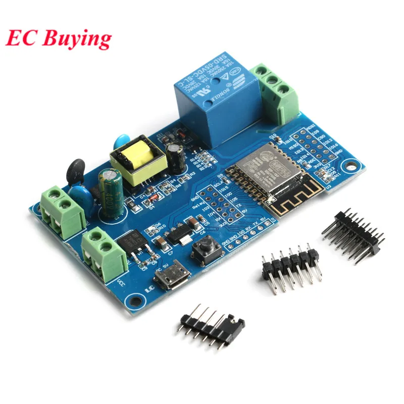
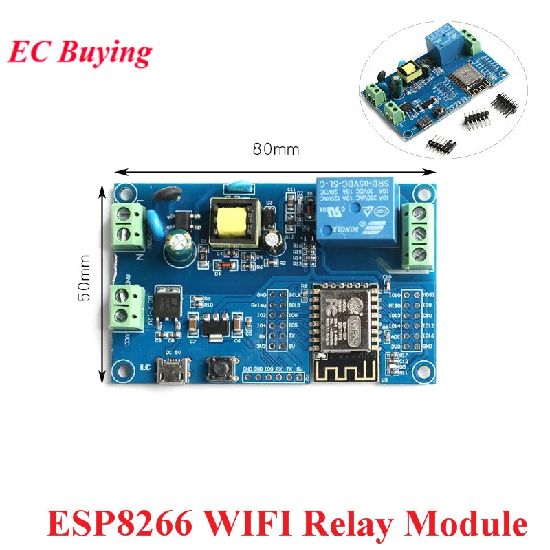
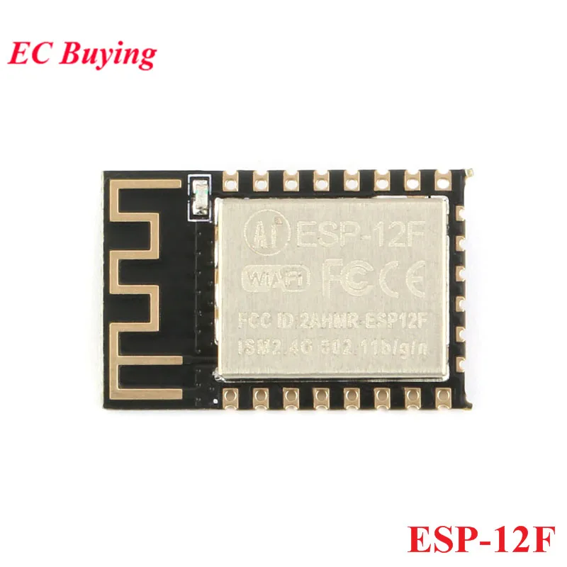
 Note: ESP-12F, we prepare it for customers who need it. If you don't need it, please don't place an order. No refund will be made if the selection is wrong. Thanks for your understanding!The ESP8266 single-channel relay development board is equipped with an ESP-1 2F WIFI module, all I/O ports are exported, and supports various power supply methods such as AC90-250V/DC7-12V/USB 5V. Suitable for ESP8266 secondary development and learning, smart home wireless control and other occasions.1. Onboard mature and stable ESP-12F Wifi module, large capacity 4M Byte Flash2. The I/O port and UART program download port of the WiFi module are all led out, which is convenient for secondary development3. Onboard AC-DC power supply module, power supply mode supports AC90-250V/DC7-1 2V/USB5V4. Onboard WiFi module RST reset button5. ESP-12F supports the use of development tools such as Eclipse6. Onboard 1 5V relay, output switch signal, suitable for controlling the working voltageLoad within AC 250V/DC 30V7. Onboard power indicator, programmable LED and relay indicator
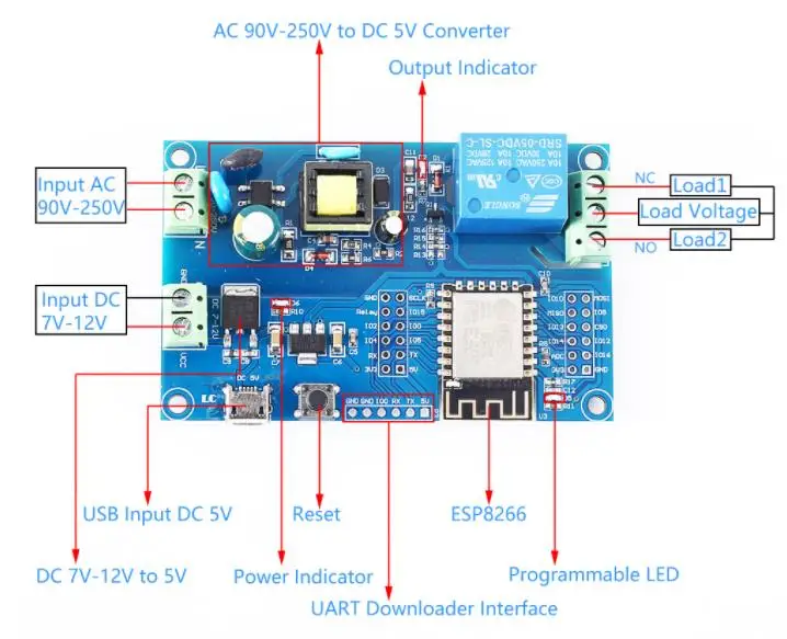
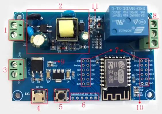
1.L, N: AC90-250V power supply
2.AC90-250V to DC5V switching power supply (when using AC power supply, please don't touch it directly with your hands!!)
3.VCC, GND: DC7-12V power supply;
4.Micro USB: DC5V USB power supply;
Note: AC90-250V, DC7-12V, DC5V USB can choose one of three power supply modes.
5.6X6mm button: ESP8266 reset button;
6. UART program download port: ESP8266's GND, RX, Tx, 5V are respectively connected to the external TL serial port module's GND, TX, RX, 5V, 100 must be connected to GND when downloading, and then disconnect the I00 and GND after the download is completeconnection;
7. GPIO pin header leads to the port;
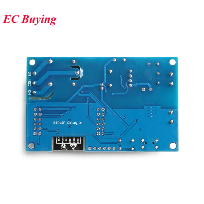
8. Relay output:
Normally closed, the relay is short-connected with COM before the pull-in, and hangs in the air after pull-in;
COM: public end;
NO: Normally open end, the relay is suspended before being closed, and shorted to COM after being closed.
9. Power indicator LED;
10. Programmable LED;
11. Relay indicator LED: lights up when it is closed.
GPIO lead port introduction:2.AC90-250V to DC5V switching power supply (when using AC power supply, please don't touch it directly with your hands!!)
3.VCC, GND: DC7-12V power supply;
4.Micro USB: DC5V USB power supply;
Note: AC90-250V, DC7-12V, DC5V USB can choose one of three power supply modes.
5.6X6mm button: ESP8266 reset button;
6. UART program download port: ESP8266's GND, RX, Tx, 5V are respectively connected to the external TL serial port module's GND, TX, RX, 5V, 100 must be connected to GND when downloading, and then disconnect the I00 and GND after the download is completeconnection;
7. GPIO pin header leads to the port;
8. Relay output:
Normally closed, the relay is short-connected with COM before the pull-in, and hangs in the air after pull-in;
COM: public end;
NO: Normally open end, the relay is suspended before being closed, and shorted to COM after being closed.
9. Power indicator LED;
10. Programmable LED;
11. Relay indicator LED: lights up when it is closed.
1. GND: power ground 2. Relay: Relay drive port, IO5 drive is used by default. If you want to use other IO to drive the relay, you can remove R14 and then connect the I/O of the drive relay to this Relay pin 3.IO2: GPIO2: UARTI-TXD 4.IO4: GPIO4 5.RX: UARTO-RXD: GPIO3 6.3V3: 3.3V power supply 7. SCLK: clock 8.IO15: GPIO15: MTDO; HSPICS; UARTO-RTS 9.IO0: GPIO0 10.IO5: GPIO5 11.TX: UARTO-TXD; GPIO1 12.5V: 5V power supply 13.IO10: GPIO10 14.MISO: Slave output and host input 15.IO13: GPIO13; HSPI-MOSI; UARTO-CTS 16.1IO14: GPIO14; HSPI-CLK 17. ADC: A/D conversion result. Input voltage range: 0~1V, value range: 0~1024 18.3V3: 3.3V power supply 19.MOSI: Host output and slave input 20.IO9: GPIO9 21. CSO: Chip selection 22.IO12: GPIO12; HSPI-MISO 23.IO16: GPIO16 24.GND: power ground