Enviado desde
Color
Descripción
Technical parameters:
1、Input voltage:10V-36VDC(wide range)
2、Output power maximum:150W
3, the maximum continuous current 5A, overload short-circuit protection current 8A, short-circuit time does not exceed 30 seconds
4、PWM pulse width modulation range:0%-100% Size Description
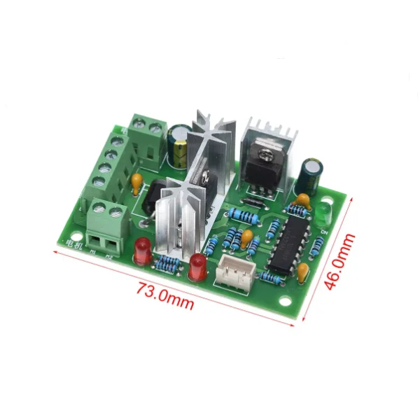
Dimensions:Length and width 73.5mm*45.5mm Height about 27mm Center distance of mounting holes 63.5mm*36.5mm Positioning hole diameter 3.5mm
Net weight:60
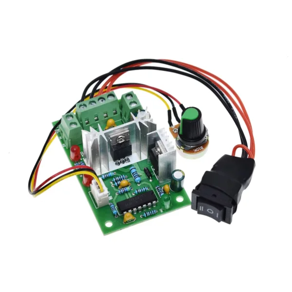
Products are equipped with external speed knob
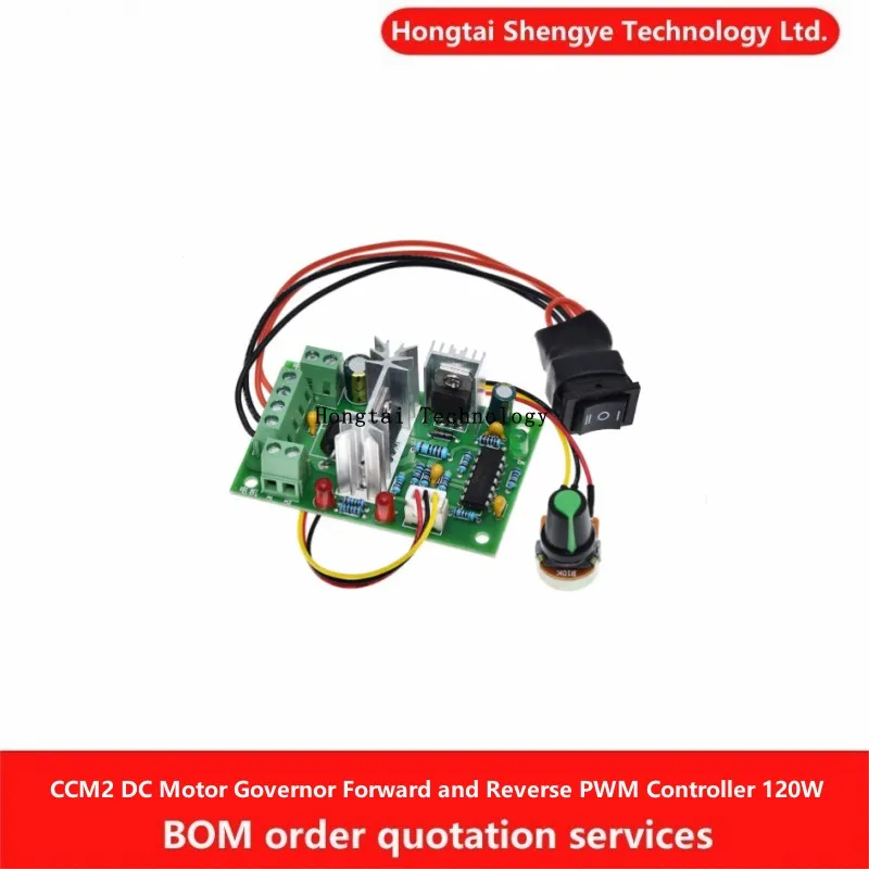
Forward and reverse control, (positive stop reverse) products are equipped with forward and reverse switch using the original chip, filter capacitors using monolithic capacitors, circuit stability and reliability. Can meet the needs of 60W-150W motor this governor using PWM speed control technology, with high conversion efficiency, wide speed range and stable performance characteristics. Speed controller all use imported STMicroelectronics original chip, factory voltage, current, function and other tests, circuit stability and reliability.
Use of wiring.
1, connect the power cord to ensure that the forward and reverse switch is located in the middle of the zero position, connect the DC power supply to ensure that the DC power supply voltage range is greater than 10V, less than 36V, to ensure that the power supply output power to meet the needs of the motor work. DC power supply positive and negative terminals do not reverse, otherwise the governor may be damaged.
2, connect the motor, motor line can not be divided into positive and negative
3, adjust the switch, positive and negative switch is used to control the direction of the motor speed, when the switch is located in the zero position, the motor stops.
4, potentiometer knob, adjust the potentiometer knob can change the governor output duty cycle, motor speed change
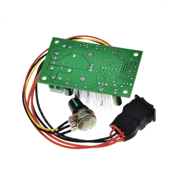
Using 0-10V external voltage control wiring instructions
This governor supports the use of external DC voltage control speed control, the use of the following steps
Steps are as follows
1. Remove the potentiometer. (You can decide to remove the potentiometer from one side of the circuit board or the other side of the potentiometer according to your needs.)
2、Connect the 0-10V DC control signal to the middle pin of the potentiometer. 3、Connect the ground wire of the 0-10V DC control signal to the right pin of the potentiometer.