
En Stock
125038 €
Con la garantía de 
Color
4 unidades vendidas
Última actualización: 2026-03-04T01:07:13.602Z
Descripción
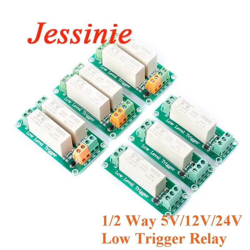
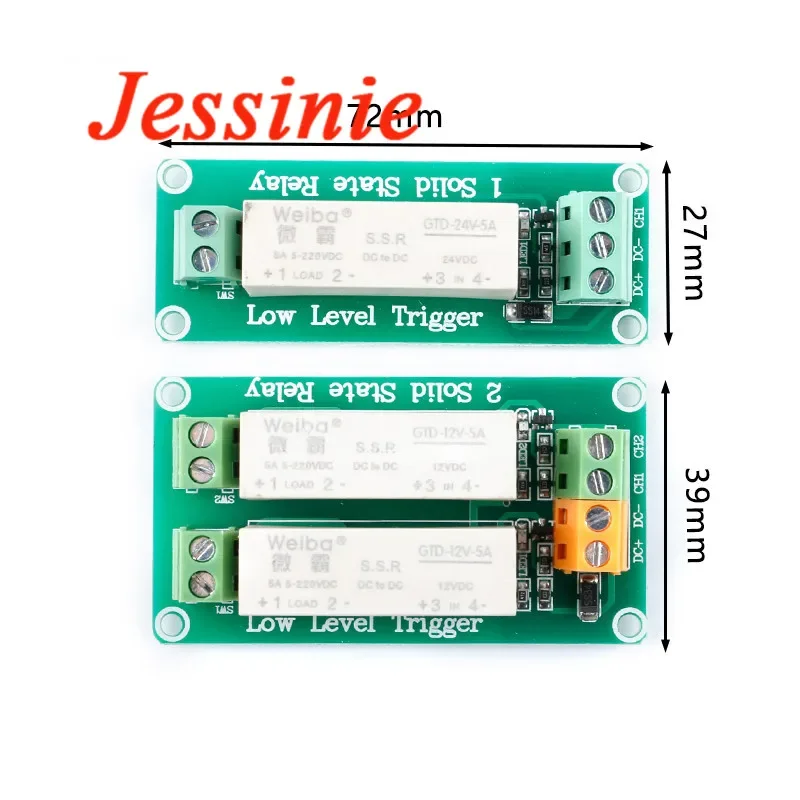
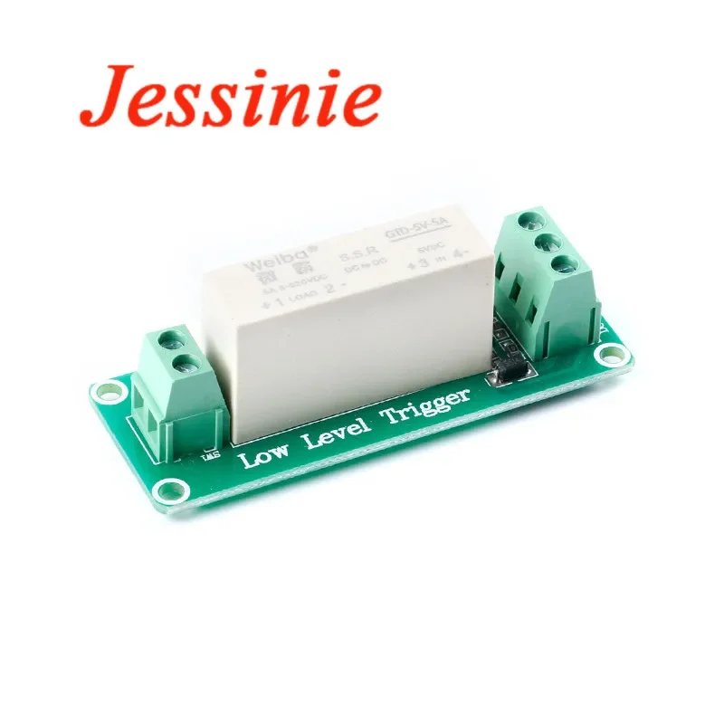
A relay is an electrical control device, which is an electrical appliance that causes the controlled quantity to undergo a predetermined step change in the electrical output circuit when the input quantity (excitation setting) changes to meet the specified requirements. It has an interactive relationship between the control system (also called the input loop) and the controlled system (also called the output loop). Usually used in automated control circuits, it actually uses small current to control a kind of "automatic switch" that controls high-current operation. Therefore, it plays the role of automatic adjustment, safety protection, and conversion circuit in the circuit.Parameter:Trigger mode: low level triggerTrigger current: 2mAPower supply voltage: 5V/12V/24VQuiescent current: 0mAMaximum working current: 1 way 12.5mA/2 way 20.5mALoad voltage: 5-220VDCLoad current: 5AMaximum switching frequency: ≤ 5KHzProduct positioning hole: 1 way 24.5*69.5mm/2 way 36.5*69.5mmTrigger voltage:5V low level trigger module: 0-1. 5VDC relay is turned on (ON), 3-5VDCRelay off (OFF)12V low level trigger module: 0-4. 5VDC relay on (ON), 5. 5-12VDC relay off (OFF)24V low level trigger module: 0-8. 5VDC relay connected (ON) 10-24VDC relay disconnected (OFF)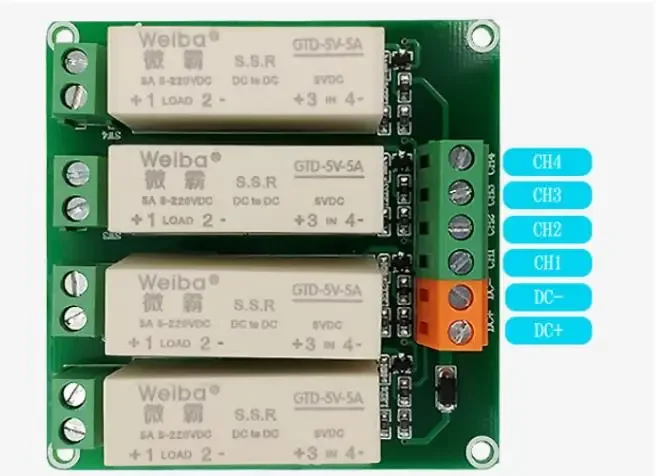 DC+: positive supply voltageDC-: negative supply voltageCH1: The first trigger signal terminalCH2: The second trigger signal terminalCH3: The third trigger signal terminalCH4: The fourth trigger signal terminalNote: The CH terminal is the trigger terminal of the module. When there is a trigger signal, the output switches (A, B) of the solid state relay will be closed, and the load will be turned on.
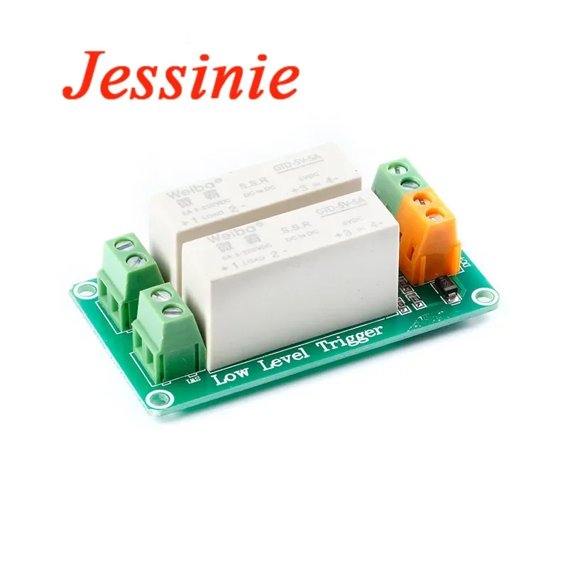
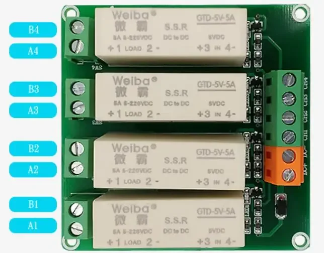
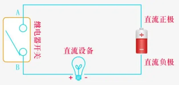 The relay is controlled by the terminal A and B port is just a switch. It should be noted that the A port is connected to the positive pole of the power supply, and the B port is connected to the positive pole of the required equipment. If A and B are connected reversely, the relay will not be controlled!Precautions1. Please use the power supply and load within the parameter range, and do not use it beyond the range.2. The rated load and life are a reference value and will vary greatly according to different environmental factors, load properties and types, so it is best to confirm in actual or simulated actual use.3. The load capacity of the module is greatly affected by the ambient temperature and its own temperature rise. It is only necessary to use air convection to dissipate heat according to the actual working environment conditions, and it is required to install in a good convection environment.4. Electrical durability at high temperature: When the module is used at high temperature, the electrical durability will be lower than that at room temperature, so please confirm it in actual use.5. The solid state relay module is divided into AC and DC. This is a DC solid state relay, which cannot control AC loads, but can only control DC loads.6. This solid state relay uses a multimeter to measure the resistance at the output terminal. One side of the resistance is large and the other is small when the meter pen is exchanged, because there is a diode for protection inside. When the resistance is measured with a multimeter, the forward resistance of the diode is measured. normal phenomenon. Solid state relays are different from electromagnetic relays. This switch without contacts is designed using the shut-off function of electronic components. Measuring resistance is not accurate. It is equivalent to a switch in the application circuit; it is not possible to measure the voltage across the solid state relay with a multimeter. Stepping down is the same as turning on.7. The output terminal of this solid-state relay module has polarity, and the output terminal should be divided into different directions, not reversed, otherwise the relay will be easily burned out.
DC+: positive supply voltageDC-: negative supply voltageCH1: The first trigger signal terminalCH2: The second trigger signal terminalCH3: The third trigger signal terminalCH4: The fourth trigger signal terminalNote: The CH terminal is the trigger terminal of the module. When there is a trigger signal, the output switches (A, B) of the solid state relay will be closed, and the load will be turned on.The relay is controlled by the terminal A and B port is just a switch. It should be noted that the A port is connected to the positive pole of the power supply, and the B port is connected to the positive pole of the required equipment. If A and B are connected reversely, the relay will not be controlled!Precautions1. Please use the power supply and load within the parameter range, and do not use it beyond the range.2. The rated load and life are a reference value and will vary greatly according to different environmental factors, load properties and types, so it is best to confirm in actual or simulated actual use.3. The load capacity of the module is greatly affected by the ambient temperature and its own temperature rise. It is only necessary to use air convection to dissipate heat according to the actual working environment conditions, and it is required to install in a good convection environment.4. Electrical durability at high temperature: When the module is used at high temperature, the electrical durability will be lower than that at room temperature, so please confirm it in actual use.5. The solid state relay module is divided into AC and DC. This is a DC solid state relay, which cannot control AC loads, but can only control DC loads.6. This solid state relay uses a multimeter to measure the resistance at the output terminal. One side of the resistance is large and the other is small when the meter pen is exchanged, because there is a diode for protection inside. When the resistance is measured with a multimeter, the forward resistance of the diode is measured. normal phenomenon. Solid state relays are different from electromagnetic relays. This switch without contacts is designed using the shut-off function of electronic components. Measuring resistance is not accurate. It is equivalent to a switch in the application circuit; it is not possible to measure the voltage across the solid state relay with a multimeter. Stepping down is the same as turning on.7. The output terminal of this solid-state relay module has polarity, and the output terminal should be divided into different directions, not reversed, otherwise the relay will be easily burned out.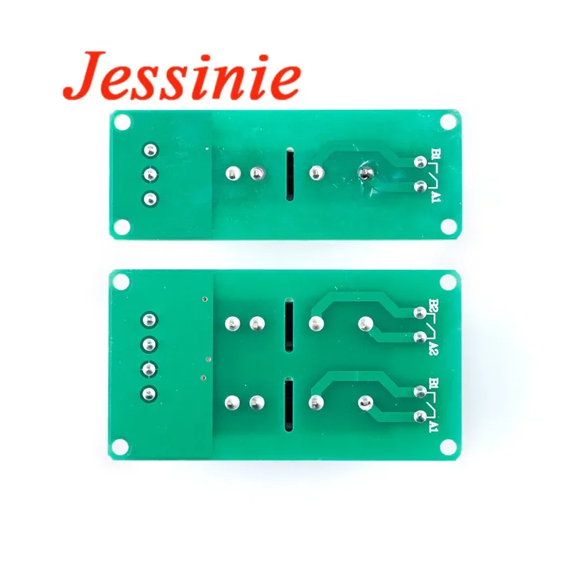

Opiniones de clientes
1 opinionesА
2 de julio de 2025
Variante: Color:1-Channel 12V